1 Scope
This document describes how to diagnose errors with the STABILO Digipen, Version 6, and how to dis- and reassemble the product for maintenance. Further sections cover proper shipping and disposal procedures. While Version 6 pens are white/blue, the earlier Version 5 pens are white/orange. Repairing both versions is very similar, so no dedicated Version 5 Repair Manual exists.
2 Troubleshooting
2.1 Loss of Bluetooth-Connection
Since the Digipen uses up a large part of the possible Bluetooth Low Energy connection bandwidth, several Bluetooth devices in the immediate vicinity may reduce the available bandwidth so much that the remaining bandwidth for the Digipen is insufficient. Turn off unnecessary Bluetooth wireless technology enabled devices if your app is unexpectedly disconnected from the Digipen.
2.2 Unstable Bluetooth Connection
Sometimes it may help to reset the bonding information on both the pen and the tablet. For the Digipen to reset bonding infromation, hold the on/off switch depressed after switching it on. You need to press the switch continuously for at least 12 seconds until you see a violet double blink which indictates that the bonding information has been reset.
2.3 Calibration fails
The calibration requires sufficient coverage of possible directions during the calibration of the magnetic sensors. It will allow for up to 2500 measurements but if that still leaves too many directions uncovered, the calibration ends with an error. Please repeat the calibration and pay attention to the direction where the small rectangles light up. Try to move it into the dark areas of the rectangle in order to lighten up as much of the rectangles as possible.
2.4 LED Codes
System status and error conditions are signaled by the LED. By mixing the output of the red, green and blue LED, different colors can be generated:
red + green: Yellow;
red + blue: Violet;
green + blue: Turquoise
red + blue: Violet;
green + blue: Turquoise
|
State
|
USB cable
|
Red LED
|
Green LED
|
Blue LED
|
Comment
|
|---|---|---|---|---|---|
|
off
|
removed
|
off
|
off
|
off
|
—
|
|
off, battery not fully charged
|
inserted
|
slowly swelling on and off
|
slowly swelling on and off, half power
|
off
|
charge in progress
|
|
brief flashes
|
brief flashes
|
off
|
overtemperature
|
||
|
off, battery fully charged
|
inserted
|
off
|
slowly swelling on and off
|
off
|
charge completed
|
|
on, Bootloader only
|
both
|
off
|
on
|
on
|
advertising
|
|
off
|
flashing
|
flashing
|
connected
|
||
|
Booting
|
both
|
off
|
off
|
two times flashing
|
—
|
|
BLE advertising
|
removed
|
off
|
off
|
slowly swelling on and off
|
—
|
|
BLE connected
|
removed
|
off
|
off
|
on
|
—
|
|
on
|
removed
|
slowly swelling on and off
|
off
|
slowly swelling on and off
|
low battery
|
|
two times flashing
|
off
|
two times flashing
|
pairing information erased
|
||
|
flashing irregularly
|
off
|
flashing irregularly
|
receiving new firmware
|
||
|
on
|
removed
|
double blinking
|
double blinking, half power
|
off
|
hardware defect
|
|
inserted
|
on
|
off
|
on
|
A slow orange flashing of the LED during charging indicates a normal charging process. A quick single orange flashing during charging indicates too high internal temperatures. Please locate the pen in a cool and shady spot, let it cool down for a few minutes with the charger disconnected and then continue with the charging. If, however, the LED shows a periodic orange double flash after the pen is switched on, the firmware has registered a hardware failure during the self-test of the electronics of the pen. Switch the pen off and on again. If the flashing still occurs after a restart, please contact STABILO support.
A purple flashing LED during operation indicates a deeply discharged battery. The pen will shut down shortly thereafter and should be charged immediately. A purple flashing LED during charging indicates that the battery voltage is below the normal range. This is normal after a deep discharge and will change to a steady orange light when the voltage has risen sufficiently. A purple LED can also be observed when copying a new firmware and is completely normal.
2.5 Reset
If the LED light does not respond when the pen is switched on, please check whether the battery needs to be charged. If connecting the pen to a USB power source still does not switch on the LED, you might try to re-start the boot process. you do this by inserting a wire, e.g. from a straightened paper clip, into the hole next to the lanyard opening of the USB plug as shown in Figure 1. Please only insert the wire for no more than 8 mm in order to avoid damaging the electronic components inside. Doing this once is enough!
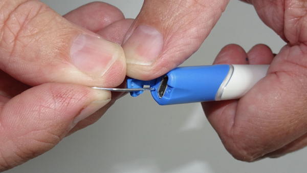
Figure 1: Resetting the pen
If this does not help, the battery is probably damaged. Please send the pen in for repairs as described in section 2.6.
Caution: Do not push anything more than 8 mm into the reset hole!
If you push further, the sensitive electronics will be damaged.
2.6 The time between two battery charges becomes noticeably shorter
The Digipen contains a high-quality lithium-ion battery that can run for hundreds of charging cycles. If you find that its capacity decreases noticeably, STABILO can install a new battery for a processing fee. Due to the compact design of the pen, we advise against changing the battery yourself.
Caution: Danger of explosion due to improper battery replacement!
Disposal of used batteries according to instructions.
(Not really, but we are legally obliged to print these scary warnings)
Please send the pen to STABILO to replace the battery. The address for this is:
Schwan-STABILO Schwanhäußer GmbH & Co. KG
Industriestraße 47
91781 Weißenburg
Germany
Alternatively, you may try to disassemble the pen and insert a new battery yourself. Please follow the instructions in section 5.
3 List of Parts
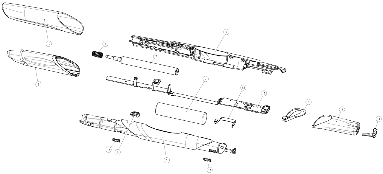
Figure 2: Digipen version 6 exploded view
|
1 Left body shell
|
5 Light ring
|
10 Cap
|
|
2 Right body shell
|
6 On/off button
|
11 USB port cover
|
|
3 Soft grip zone
|
7 Writing cartridge
|
12 Battery contact spring
|
|
4 End closure
|
8 Writing cartridge spring
|
13 Processor board
|
|
9 Battery
|
14 PCB clamps
|
4 Tip Replacement
If the writing tip dries up, STABILO offers a pack of four replacement cartridges for the Digipen. Please do not try to replace the cartridge with a commercially available ballpoint pen refill – the cartridge of the Digipen was specially developed for it.
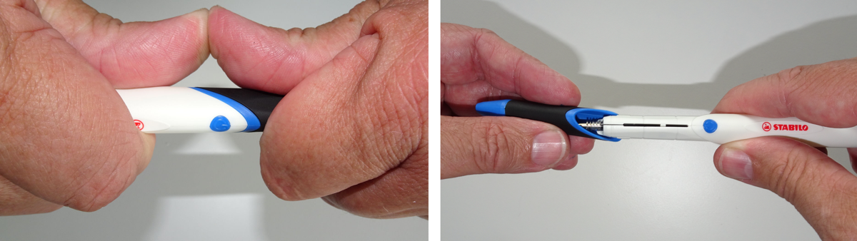
Figure 3: Removal of the grip zone part.
Left: Pushing with two thumbs, Right: Pulling off in forward direction
Left: Pushing with two thumbs, Right: Pulling off in forward direction
To replace an empty cartridge, the grip zone part 3 can be pulled forward and releases the cartridge 7, which can then be easily replaced. A rotation of the grip zone part is not needed and complicates the procedure because it is guided by means of longitudinal grooves on the pen barrel. Therefore, please only move the grip zone in the direction of the pen’s longitudinal axis if you want to remove or replace it. Leave the spring on the refill and make sure you will not lose it.
To assemble the pen, please proceed in reverse order. Please make sure to slip the grip zone part onto the pen barrel in a straight way and not to rotate or twist it. There should be an audible click and no gap left between the grip zone and the barrel when the grip zone is correctly inserted.
5 Pen Disassembly
First, remove the cap 10, grip zone 3 and writing insert 7 as shown in section 4.
Next, remove the rear end cap 4 by twisting it against the pen barrel. Due to the angled interface between end cap and pen barrel, twisting works like a ramp and amplifies your force. The end cap is secured by the application of some thickened PVAC glue in the groove in the inside of the end cap in order to avoid accidental removal. Then pull the light ring 5 off.
Now you need to split the two halves 1 and 2 of the body shell. For this, grip the pen with the rear end up and place your thumbs in the cutout below the rear PCB as shown in Figure 4. Press both halves apart, starting at the rear end. Most likely, both halves will snap apart suddenly if enough force is applied. The battery might drop out, so make sure you can catch whatever falls out of the pen body when doing this.
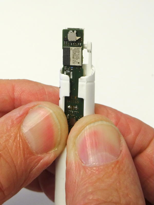
Figure 4: Splitting the two pen barrel halves
If the circuit board is still held in place by the clamps 14, twist it gently until it is released. Now the battery and circuit board can be replaced. For battery replacement use a 10440 size Li-Ion battery with an elevated plus knob. Geometrically, it should be identical to an AAA battery with 10 mm diameter and 44 mm length. Its rated voltage should be between 4.2 V when fully charged and 3.0 V when fully discharged. The nominal capacity of the battery used by STABILO is 350 mAh.
6 Pen Assembly
This assumes that the PCB is programmed and the battery spring is soldered in place. If not, please perform those steps first.
To start, pre-bend the circuit board in four places as shown in Figure 5.
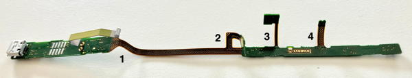
Figure 5: Pre-bent circuit board
Insert it into the left body shell, starting with the corner of the contact spring 12 as shown in Figure 6. Make sure that the contact spring is inserted into the lower groove and the cutout in the bulkhead as shown.
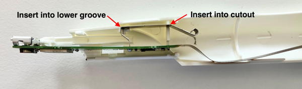
Figure 6: Correct position of the contact spring
Make sure that the USB socket is seated on the rear punch. The barrel is a few tenths of a millimeter too long between the groove for the contact spring and the punch that is supposed to hold the USB socket, so the punch must be pressed with force in front of the socket. Now secure the PCB with a bracket which is to be inserted into the rear rectangular cutout. It should completely disappear in the cutout, so no part of it is sticking outside of the barrel contour. Lock the oblong hole in the PCB in the bracket.
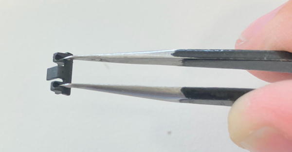
Figure 7: Using a pair of cranked tweezers, the small bracket can be comfortably handled
Next, press the front PCB into the cutout at the bottom of the bulkhead. Insert front circuit board into its cutout. Be careful of the flex line connecting both: Is it completely inside the barrel? Don’t slip the ends with the force sensors over the edge of the barrel: they like to pop off. Better bend the flex board over so that the force sensors never come into contact with the edge of the barrel. Before the flex board is fully inserted at the front, insert the pushbutton board into its recess. Fix in place with the switch cover. When that is done, insert the second bracket into the forward rectangular cutout and lock the forward PCB in it. The result should look like in Figure 8.
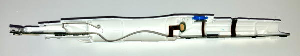
Figure 8: Now the PCB is fully inserted and secured.
Insert the battery starting with the negative pole, pressing it backwards against the contact spring so that the positive pole does not squeeze the force sensor. Press the battery against the barrel with your thumb so that it cannot slip forward. Maneuver the force sensor into position with the tweezers, then release the battery. Loop a strip of polyethylene or Tyvek around the front end of the battery, holding the ends on the outside between thumb and forefinger from now on (see picture below). Check that the negative terminal contact is sufficiently deep in the left barrel. As a rule, the end at the negative pole must again be pressed into the barrel.
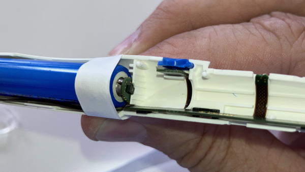
Figure 9: Keep the battery from popping out by holding it with a strip of Tyvek or PE
Now is the time to check those poins:
- Check whether the USB socket is seated correctly.
- Check that the writing force sensor is centered in its recess in the forward bulkhead of the barrel.
- Check whether the switch board and the switch cover are seated correctly.
- Check the grip force sensor for proper fit in its recess.
- Check front end of the board to make sure it is still in its groove.
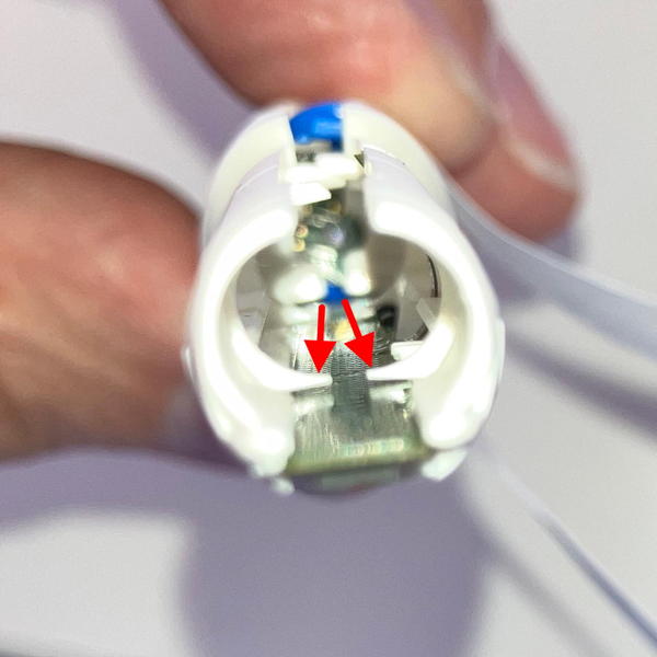
Figure 10: Check that the PCB is held down properly
Now place the right half of the barrel on the underside of the left one. Place the tongues inside each other, checking that the flex board is between the battery and the tongues along its entire length. Swing the right half of the barrel against the left half until the tips of the tangs dip into the sockets on the opposite side. Check:
- Is the writing force sensor still seated properly? Often, you still have to push it down a little so that it is centered in the cutout of the bulkhead.
- Are the two halves of the bulkhead in front of the force sensor board?
- Are all four tabs on top of the board when looking in from the front? See Figure 10 for reference.
- Does the rear board sit low enough so that it protrudes into the recess at the bottom of the contact spring bulkhead? Here, too, you usually have to help, e.g. with a bent-up paper clip (see picture below). This is used to hook under the board from below and pull it into the recess.
Press the pins for the first millimeter into the sockets, then pull out the Tyvek strip. See Figure 11 for reference which also shows the bent paper clip.
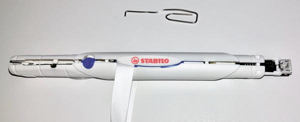
Figure 11: Pen barrel shortly before it can be closed completely. Note bent paper clip on top.
Carefully press the halves of the pen barrel together. If the button board is placed askew, it can block the halves and you cannot press the barrel together completely. To do this, you can use a wire to push the front right corner of the button board to the left from above. This will cause it to rotate and the critical back right corner will come further forward, which will help with threading. Likewise, keep checking to make sure the force sensor is centered in its cutout. To push it down, use the same paper clip (see the top of Figure 11 above) that was used to pull down the back of the board. First at the back, then at the front, press the barrel completely together. It takes some force to do this and you have to be sure that nothing blocks the assembly. Press the two punches in front of the USB socket together, because they don’t always do this by themselves. Put on the light ring and the rear end cap. If available, add the thickened PVAC glue in the end cap. Before you let the end cap snap in completely, check if the USB socket is centered and can completely enter the opening in the end cap. If it sits crooked, you can twist the end cap accordingly; then the socket will fall into the cutout provided for it. Then close the USB cover. If you do this before, you can’t see so well if the USB socket is seated correctly! Check whether the grip force sensor is correctly seated in its pocket. Replace the writing cartridge and make sure it still carries its spring, then slip on the grip zone and cap. Done.
7 Shipping the pen
7.1 Labeling of Dangerous Goods
Lithium-Ion batteries are classified by international transport law as dangerous goods. They need to pass Article 38.3 of the UN Manual and Criteria to ensure the safety of lithium polymer batteries during transportation. Details depend on the means of transportation: In the EU, the relevant regulation for road and rail transportation is ADR 2019. For air transport, the relevant regulations are IATA VA 965 part IB (for separate batteries), VA 966 part II (for batteries packed together with products that use them) and VA 967 part II (for batteries included in products), contained in the IATA Dangerous Goods Regulations (DGR). The specific stipulations for small Lithium-ion batteries included in products are:
7.2 For road and rail transport
Documentation proving the testing according to UN 38.3 must unsolicitedly be presented to everyone involved in handling the package. A proper information sheet can be downloaded here. For small batteries of less than 100 Wh and / or 500 g the labeling requirements are eased if certain preconditions are fulfilled (the Digipen battery has 1.3 Wh energy content when fully charged and weighs 10 g).
- The battery is packaged inside the article it is meant to power.
- The battery is fully enclosed in a sturdy enclosure.
- The battery is protected from being accidentally activated or short-circuited.
- Only two or fewer batteries per article, only 2 or fewer packages and less than 30 kg per shipment.
- Personnel at the sender has been trained and instructed to follow all stipulations in SV 188 (Sonderverordnung 188 der Richtlinien zur Durchführung der Gefahrgutverordnung Straße und Eisenbahn (German Federal Law))
If all requirements are met, the shipment is exempt from the remaining requirements of the ADR. No labeling is required.
7.3 For air transport
- The battery is packaged inside the article it is meant to power.
- The battery is packaged according to IATA VA 967 part II. The package fully encloses the battery and prevents it from moving inside the packaging.
- The battery is protected from being accidentally activated or short-circuited.
- Only two or fewer batteries per article, only 2 or fewer packages and less than 5 kg per shipment (35 kg for cargo aircraft).
- Personnel at the sender has been trained and instructed to follow all stipulations in IATA VA 967.
- No other dangerous goods are packed together with the lithium batteries in the same package.
If all requirements are met, no labeling and no declaration in the Airway Bill is required. Also, the 1.2 m drop test required in Packing Instructions 966 and 969 Section II is not required.
If the package contains more than 2 batteries, a warning label according to EN 3481 (minimum dimension 110 x 120 mm) must be attached on the outside of the shipping container. The label must contain a telephone number which can be reached for further information. The separate articles must be prevented from accidentally shifting inside the shipping container.
If each product contains only one single-cell battery, up to 4 products can be packed together in one package without requiring a warning label or a warning notice on the airway bill. The Digipen battery is of the single-cell type, so up to 4 separately packed pens may be shipped without a warning label.
7.4 Customs tariff number
In international shipping, the pen is to be characterized by a customs tariff number. This is 8471 6070 and denotes input or output units for automatic data-processing machines, whether or not containing storage units in the same housing (excluding keyboards). The country of origin is Germany (09).
8 Disposal of Electronic Products and Components
The Digipen and its electronic components should only be disposed of at special collection sites for electronic waste. Please consult your local administration if you are unsure where to find the nearest one.
The European Union’s WEEE Directive 2012/19/EU on Waste of Electronic and Electrical Equipment requires that the WEEE symbol must be placed on the Digipen. The product is registered in Germany as 31959237, in Austria under GLN 9008391728580 and in Luxembourg under MA1159 for the electronics and M1049 for the battery. The registration number for the battery registration in Germany is DE 97290751 and in Austria it is registered with ERA as 40466.
European WEEE (Waste Electrical and Electronic Equipment) regulations are aimed at reducing the environmental impact of electrical and electronic equipment. These regulations require manufacturers of such equipment to properly label, register and report their products, as well as provide information to consumers about proper disposal of the equipment. Additionally, manufacturers are responsible for ensuring that the equipment is recycled in an environmentally friendly manner, and for providing financial contributions towards waste collection and recycling. Finally, the regulations also require that retailers provide information and advice to consumers on the safe and proper disposal of their products.
9 General technical data
|
General operating temperature
|
0° C to 40° C
|
|
Battery charging temperature
|
5° C to 35° C
|
|
storage temperature (minutes)
|
-20° C to + 70° C
|
|
Storage temperature for longer periods
|
up to 1 month: -20° C to + 40° C
|
|
more than 1 month: -20° C to + 35° C
|
|
|
Relative humidity during operation
|
20% up to 85%
|
|
Relative humidity during storage
|
10% up to 90%
|
|
Operating and storage location
|
Dust-free and dry environment, closed spaces
|
|
Size (L × D)
|
167 × 15.0 mm (including cap)
|
|
Mass
|
about 25 g
|
|
Radio protocol
|
Bluetooth® Low Energy 5
|
|
Frequency bands
|
2.402 GHz to 2.480 GHz in 20 MHz raster
|
|
Maximum transmission power
|
1mW / 0dBm
|
|
Battery type
|
Lithium Ion Battery type 10440 (AAA size)
|
|
Charging time (typical)
|
3 hours
|
|
Charging time (maximum)
|
4 hours
|
|
Maximum charge current at USB cable
|
1 Ampère
|
|
Continuous operation time (typical)
|
15 hours
|
|
Force measurement
|
4096 steps
|
|
Tilt range
|
any
|